Reptilecam
Abstract - Raspberry Pi based project aiming to provide remote environmental control and monitoring for reptile keepers. The system provides a live video feed of the enclosure, real-time temperature and humidity monitoring, and configuration of 3 power outlets.
Presentation
Introduction
Reptiles are a popular type of exotic pets that many individuals enjoy keeping. However, most reptiles have a complex set of environmental requirements that must be satisfied if the reptile is to enjoy a long and happy life. Most reptiles have strict temperature, light and humidity requirements which vary dramatically between species. In order to maintain a suitable environment for their pet, most reptile keepers will need a variety of heating and lighting devices, as well as thermostats and timers to keep these devices operating in the correct range.
To illustrate this problem, we take the example of the popular lizard pet, the beaded dragon. Bearded dragons are native to the deserts of Australia and therefore need hot, bright and dry conditions. In order to maintain these conditions, a bearded dragon keep would typically require a basking lamp, a heater and a UV lamp. The heater is connected to an on/off thermostat which turns the heater on if the temperature is below the target, and off if the temperature is above it. The basking and UV lamps are both connected to a timer in order to create a day/night cycle for the reptile. In addition to this, the basking lamp is connected to a dimming thermostat, which dims the lamp if the enclosure gets too hot. The dimming thermostat is needed instead of an on/off thermostat so that the basking light is not constantly flickering (which reduces its lifespan) and to avoid confusing the reptile who may think that its night when in fact the enclosure has just become too hot.
This project proposes an all-in-one device that could replace the assortment of thermostats and timers needed to drive heating/lighting devices and offer the user a convenient central location to configure the environment. In addition to this, the device offers remote monitoring enabling the user to view a live video feed, take photographs of their pet, and check the temperature and humidity of the enclosure.
Interaction Overview
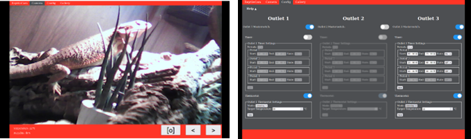
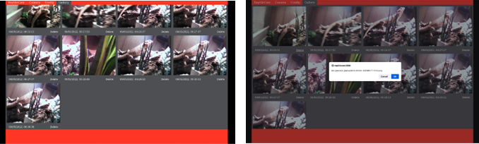
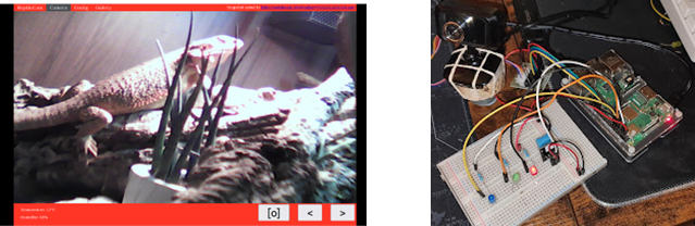
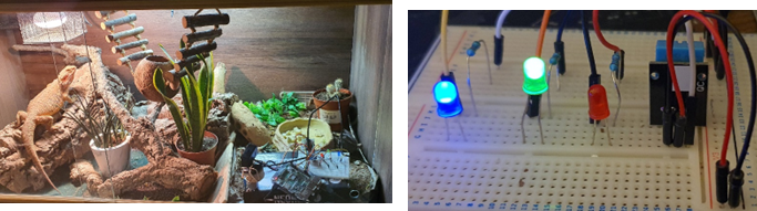
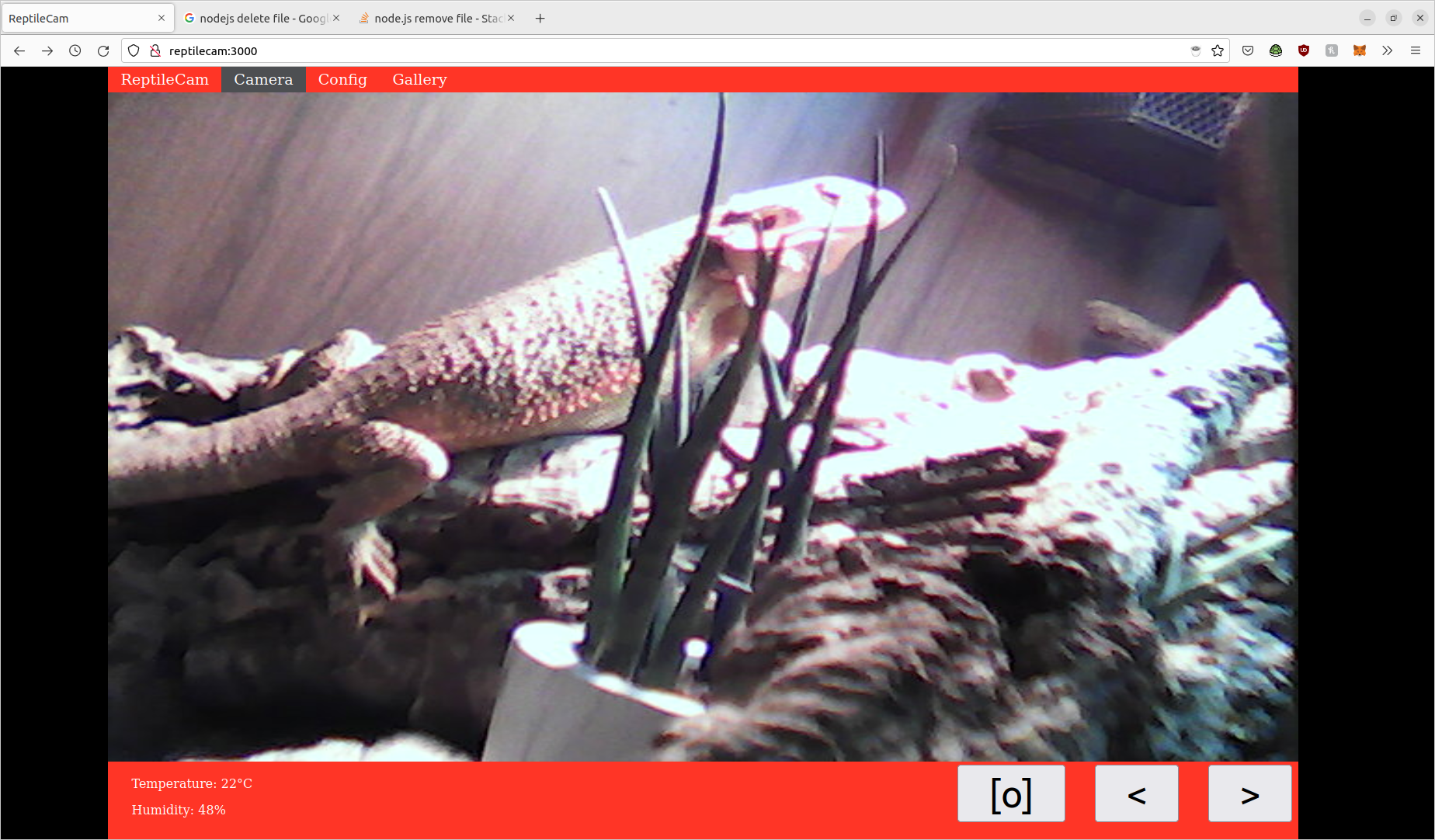
Figure 1 shows the homepage for the system. From here, the user can view the current temperature and humidity of the enclosure (bottom left), watch a video feed of their pet, pan the camera left and right using the ‘<’ and ‘>’ buttons and take a snapshot by pressing the ‘[o]’ button. Figure 5 shows the screen immediately after taking a snapshot (notice the notification in the top right). Users can navigate to other pages using the navigation bar at the top of the page. Figure 2 shows the configuration screen where the settings for each of the power outlets can be configured. A help screen is shown if the user clicks help. Figure 3 shows the gallery page where users can view and delete their snapshots. Figure 4 shows the confirmation screen shown when a user attempts to delete a snapshot. Figure 6 shows the hardware components making up the system and figure 7 shows these inside a bearded dragon enclosure. Figure 8 shows a close up of the three power outlets simulated by LEDs.
Parts List
Hardware
- Raspberry Pi (3rd generation or newer)
- Raspberry Pi power supply
- USB Webcam
- Breadboard
- Stepper motor
- Stepper motor driver
- DHT11 sensor
- 3 x 10K resistors
- 3 x LEDs (ideally different colours)
- Micro SD card
- Assorted jumper leads
Software
- Raspberry Pi OS
- SSH (optional, but peripherals needed otherwise)
- Node.js [1], NPM (Node Package Manager), GStream, PhantomJS
- Web browser
- IDE
- Git (optional)
Process
Raspberry Pi setup
Before starting on the project, the Raspberry Pi needed to be set up. The first stage of this is preparing an SD card containing the Raspberry Pi OS [2]. Raspberry Pi OS is based on Debian but optimised for the Pi. Once this is done, the Pi can be booted and configured. A keyboard and monitor were needed at first, but these can be used to set up WiFi and SSH server so that the Pi can be accessed remotely for the rest of the development process. Finally, the software dependencies (node.js, npm, phantomJS, GStream) for the project were installed.
Video Feed
The first stage of the project was configuring the Raspberry Pi to stream the video from the webcam, over the network. Various methods were experimented with, but in the end the Node package ‘livecam’ [3] was selected. Livecam invokes GStreamer [4] to capture the video from the webcam and streams it via WebSocket. Livecam then hosts a webpage containing a single image and a simple JavaScript script that changes the image to the latest frame each time a new frame is received.
Once this is done, the Pi is hosting a webpage that contains a live feed from the webcam. I initially completed this step using my 1st generation Pi which was not powerful enough to handle live streaming and this resulted in massive latency and choppy video. Luckily, I was able to procure a 3rd generation Pi for the remainder of the project.
Camera Mobility
The next step of the project was providing the user with some way to move the camera around. This was achieved by attaching the webcam to a stepper motor and then providing the user with controls to rotate the stepper in either direction.
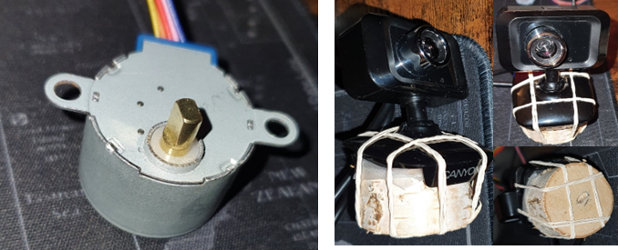
The first challenge was finding a suitable mount for the webcam. The stepper motor does not have a standard sized rod, as shown in figure 9, so there were no off-the-shelf mounting solutions available. I was able to find a 3D printed wheel that could have done the job, but without access to a 3D printer, I ended up pursuing a much lower tech option. I chiselled a slot into a small piece of wood and then attached the webcam to the wood using elastic bands. This is shown in figure 10. The rod does not fit in the slot perfectly and it’s a little wobbly, but it gets the job done.
Once the camera is securely mounted to the stepper motor, the stepper motor could be wired up to the Pi. The stepper motor was connected to a ULN2003 stepper motor driver module, and the driver outputs were connected to the 4 pins on the Pi’s GPIO. The driver handles the details of operating the magnets internal to the motor, and the Pi just has to turn the driver pins high and low in a sequence. This is achieved by using the ‘PIGPIO’ [5] node package, which provides a JavaScript interface to the GPIO.
Code to move the camera left and right was developed and placed in web API routes. A simple website was then created that contains an iframe pointing to the livecam stream, and two buttons: one for left and one for right. The buttons call the relevant API routes meaning that the user now has a live video feed and is able to pan the camera left and right. The rest of the web functionality of the system is built upon this webpage.
Temperature and Humidity
Temperature and humidity readings are provided by the DHT11 sensor. This sensor was connected to a breadboard and then wired to the Pi’s GPIO. The node package ‘node-dht-sensor’ [6] was employed to decode the output from the sensor. These details were then incorporated onto the website so that the user can view the livecam, pan the camera and also view the current temperature and humidity of the enclosure.
At this stage in the development process, some visual improvements were made to make the system more aesthetically pleasing. A header was added to allow navigation between the home page and other (to be developed) pages. The feed was styled such that a 16:9 aspect ratio would always be maintained to avoid distorting the image. The camera controls and sensor information were placed in the footer of the page and red and black background colours were added to give the webpage a more professional feel. By the end of this visual improvement process, the home page began to look very similar to figure 1.
Power Outlets
Originally, the three power outlets were intended to be full 240V AC mains power outlets, however, due to safety concerns, simulation was employed instead. The three power outlets for the prototype were simulated by 3 LEDs. Outlets 1,2 and 3 are simulated by red, green and blue LEDs respectively. The positive terminal of each of these LEDs are then connected to a dedicated pin on the Pi’s GPIO. The negative terminals are connected to 10K resistors which in turn are connected to the Pi’s ground. This is shown in figure 8.
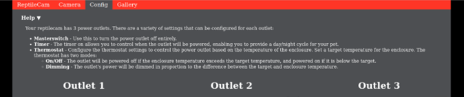
The configuration page, shown in figure 2, was developed to enable users to program a variety of configurations for their power outlets. Each outlet has a master switch used to turn the power outlet on or off. CSS greyscale and blur filters are used to show visually when a power outlet is switched off. The user then has the option of enabling a timer and/or thermostat for each outlet. If a timer or thermostat is switched off, the form containing the configuration for that element will also be grey-out to show visually that the option is disabled.
The timers support up to four time periods, and the outlet can be switched on or off for each of those periods. Most users will only require 2 periods, one for day and one for night, but there may be specialist cases where more are required.
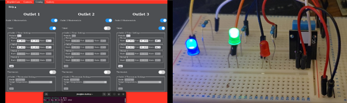
Figure 11 shows a sample timer configuration and corresponding output. All three outlets are turned on. Outlet 2 (green) does not have a timer and so is permanently on. The timer for outlet 1 (red) is turned on with two periods. The outlet is on for period 1 between 09:00 and 00:00, and off for period 2 between 00:00 and 09:00. The current time, shown in the terminal window, is 00:55 and therefore the outlet is off. The timer is also on for outlet 3 (blue) also with two periods. The timer is off for period 1 between 09:00 and 00:00 and on for period 2 between 00:00 to 09:00, outlet 3 is therefore on.
The thermostat has a target temperature and two modes: on/off and dimming. In on/off mode, the outlet will simply be turned off if the temperature exceeds the target temperature. In dimming mode, the amount of power supplied to the power outlet will be scaled linearly in accordance to difference between the target temperature and the current temperature. If the current temperature is more than 5 degrees above the target the outlet is switched off completely, and the outlet is fully powered if the current temperature is more than 5 degrees below the target. The percentage power is given by equation 1.
Power (%) = 50 – ((temperature – target) * 10) (1)
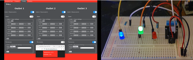
Figure 12 shows a sample thermostat configuration and corresponding outputs. All three outlets are turned on. Outlet 2 (green) has no timer or thermostat and so is permanently on. The thermostat option is turned on for outlets 1 (red) and 3 (blue). The target temperature for both outlets is the same at 17 degrees, however outlet 1 is in on/off mode and outlet 3 is in dimming mode. The current temperature is 20 degrees, therefore, outlet 1 is off completely, whilst outlet 3 is on but dimmed. The dimming is apparent when comparing figures 11 and 12.
The settings for each outlet are stored in a dedicated JSON file. Anytime a user modifies the settings, the updated settings are sent to the Pi via a web API route and the JSON files are updated. The outlets are then powered according to the current configuration. The power outputs are adjusted every time a new configuration is received, or every second.
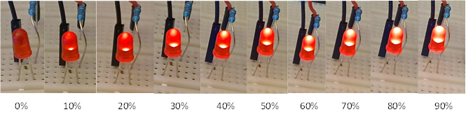
GPIO is used to power the LEDs from the PI’s GPIO. PIGPIO includes a software PWM feature which enables Pulse Width Modulation even on pins that do not have hardware support for PWM. Even though this places additional strain on the CPU, this is a welcome feature as the Pi only has 2 hardware-enabled PWM pins. Figure 13 shows outlet 1 at various percentage power levels using Software PWM as used in the prototype.
A help screen was also provided to explain how to use the system to new users. This help screen is hidden by default, but can be shown by clicking help. The help screen is shown in figure 14.
Gallery and Snapshots
The final step in developing the system was providing a means for users to save images of their pet via the web interface. This was achieved using the node package ‘node-webshot’ [7]. Webshot uses the headless web browser phantomJS [8] to navigate to and take a screenshot of a given URL. A ‘capture’ web API route is then provided. When this route is used, it will use webshot to take a screenshot of the livecam feed and save it in a ‘gallery’ folder.
A button was added to the homepage to enable users to take snapshots. When the user presses the button, the API route is used to save the snapshot. A notification informing the user of the URL of the image is then shown in the navigation bar as shown in figure 5.
A second API route was implemented that simply returns an array containing the URL of every image in the gallery folder. The gallery page (shown in figure 3) was then developed. This page simply hits this API route and uses the URLs contained within to add each to page. CSS is used to lay the images out in a grid format based on W3School's example [9].
Challenges
Initially the project was attempted with a 1st generation Raspberry Pi, however this did not have anywhere near the processing power to perform video streaming and so was replaced by a 3rd generation pi.
Taking screenshots using webshot was initially problematic and kept producing nothing but white screens. It was eventually realised that this was because webshot was taking the screenshot before the script on the webpage had been able to load the first frame of the video feed. This was rectified by introducing a delay before taking the screenshot, but this slows down the process and means it can take several seconds to capture a screenshot which is far from ideal.
Future Work
The most important improvement to be made to the system is replacing the simulated power outlets with real AC power outlets. This could be done through the use of TRIACs, optocouplers, bridge rectifiers and TRIAC-driver circuitry to control the output voltage of an input AC signal. In 2016, L.S. Tat and Y.K. Haur [10] showed that this could done by using an Arduino to control the brightness of an AC lamp.
The image quality of the video feed (and subsequent snapshots) leaves something to be desired. These aspects could be improved through a higher quality webcam and better webcam mount; however, care would have to be taken to ensure the video is still sufficiently light to be streamed by a Raspberry Pi. There is also probably a more efficient way to take snapshots of the video stream by connecting to the WebSocket directly rather than using a web browser.
Equation 1 used to govern the mapping between temperature delta and output power is linear and simplistic. It could be improved through research to find the equation used by existing dimming thermostats, or by allowing the user to configure the constants within the equation.
No security considerations have been made during this project and the system would be accessible by anyone on the network. This obviously introduces privacy concerns, especially as users would want to be able to access the system when away from home. In addition to privacy concerns, this kind of unrestricted access opens up the possibility for intruders to maliciously change the enclosure configuration which could have life threatening consequences for the reptile. This could be solved through a secure authentication process to access the website, and taking standard security measures such as firewalls.
Conclusion
The prototype created as part of this project is unique with nothing similar existing on the market. The system is very useful for monitoring the reptile and would be even more so if it was possible to connect the simulated power outlets to real heating devices. Once this is realised, the system will be able to replace all of the existing control systems in most reptile enclosures. The website is aesthetically pleasing and intuitive whilst also including instructions to help users to use the system. This website provides one convenient place to perform all the configuration related to the enclosure, and monitor it remotely. The system performs very well, even on the limited hardware of the Raspberry Pi. The only exception to this is the snapshot process which takes too long and should be improved in future versions.
Source Code
Source code and setup/installation instructions can be found here: https://git.jbm.fyi/jbm/reptilecam
References
|
[1] |
|
|
[2] |
|
|
[3] |
|
|
[4] |
|
|
[5] |
|
|
[6] |
|
|
[7] |
|
|
[8] |
|
|
[9] |
|
|
[10] |
Lee Siang
Tat, Yiauw Kah Haur 2016: “Remote AC Power Control by Using Microcontroller”:
https://core.ac.uk/download/pdf/235220849.pdf
|